

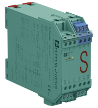
Switch Amplifier KFD2-SH-Ex1
- 1-channel isolated barrier
- 24 V DC supply (Power Rail)
- Input for approved dry contacts or SN/S1N sensors
- Relay contact output
- Fault indication output
- Line fault detection (LFD)
- Up to SIL 3 acc. to IEC/EN 61508
- Up to PL d acc. to EN/ISO 13849


Quantity

Free Shipping
Purchase on Account

Please note: All product-related documents, such as certificates, declarations of conformity, etc., which were issued prior to the conversion under the name Pepperl+Fuchs GmbH or Pepperl+Fuchs AG, also apply to Pepperl+Fuchs SE.
Datasheet excerpt: Technical data of KFD2-SH-Ex1
| General specifications | ||
|---|---|---|
| Signal type | Digital Input | |
| Functional safety related parameters | ||
| Safety Integrity Level (SIL) | SIL 3 | |
| Performance level (PL) | PL d | |
| Supply | ||
| Connection | Power Rail or terminals 22+, 23+, 24- | |
| Rated voltage | 20 ... 35 V DC | |
| Ripple | ≤ 10 % | |
| Rated current | ≤ 130 mA | |
| Power dissipation | 2.1 W | |
| Power consumption | max. 2.3 W | |
| Input | ||
| Connection side | field side | |
| Connection | terminals 10+, 12- | |
| Open circuit voltage/short-circuit current | approx. 8.4 V DC / approx. 11.7 mA | |
| Lead resistance | ≤ 50 Ω, in hazardous area cable capacitances and inductivities are to be taken into account | |
| Switching point | ||
| Relay de-energized | I < 2.1 mA and I > 5.9 mA | |
| Relay energized | 2.8 mA < I < 5.3 mA | |
| Response delay | ≤ 1 ms | |
| Output | ||
| Connection side | control side | |
| Connection | output I: terminals 13, 14 ; output II: terminals 15, 21 ; output III: terminals 16+, 17- | |
| Output I | relay , signal | |
| Contact loading | 50 V AC/1 A/cos φ > 0.7; 24 V DC/1 A resistive load | |
| Mechanical life | 50 x 106 switching cycles | |
| Output II | relay , signal | |
| Contact loading | 50 V AC/1 A/cos φ > 0.7; 24 V DC/1 A resistive load | |
| Mechanical life | 50 x 106 switching cycles | |
| Output III | electronic output, passive , fault signal | |
| Rated voltage | 10 ... 30 V DC | |
| Signal level | 1-signal: (L+) -2.5 V (7 mA, short-circuit proof) / 0-signal: blocked output (Leakage current ≤ 10 µA) |
|
| Transfer characteristics | ||
| Switching frequency | 5 Hz | |
| Galvanic isolation | ||
| Output/power supply | reinforced insulation according to IEC/EN 61010-1, rated insulation voltage 300 Veff | |
| Mutual output I, II, III | basic insulation according to IEC/EN 61010-1, rated insulation voltage 50 Veff | |
| Indicators/settings | ||
| Display elements | LEDs | |
| Labeling | space for labeling at the front | |
| Directive conformity | ||
| Electromagnetic compatibility | ||
| Directive 2014/30/EU | EN 61326-1:2013 (industrial locations) | |
| Machinery Directive | ||
| Directive 2006/42/EC | EN/ISO 13849-1:2015 | |
| Conformity | ||
| Electromagnetic compatibility | NE 21:2017 , EN 61326-3-1:2017 | |
| Degree of protection | IEC 60529:2001 | |
| Safety | IEC/EN 61508:2010 | |
| Ambient conditions | ||
| Ambient temperature | -20 ... 60 °C (-4 ... 140 °F) | |
| Mechanical specifications | ||
| Degree of protection | IP20 | |
| Connection | screw terminals | |
| Mass | approx. 280 g | |
| Dimensions | 40 x 107 x 115 mm (1.6 x 4.2 x 4.5 inch) (W x H x D) , housing type C1 | |
| Height | 107 mm | |
| Width | 40 mm | |
| Depth | 115 mm | |
| Mounting | on 35 mm DIN mounting rail acc. to EN 60715:2001 | |
| Data for application in connection with hazardous areas | ||
| EU-type examination certificate | PTB 00 ATEX 2042 | |
| Marking |  II (1)G [Ex ia Ga] IIC II (1)D [Ex ia Da] IIIC I (M1) [Ex ia Ma] I II (1)G [Ex ia Ga] IIC II (1)D [Ex ia Da] IIIC I (M1) [Ex ia Ma] I |
|
| Input | Ex ia | |
| Voltage | 9.56 V | |
| Current | 16.8 mA | |
| Power | 41 mW (linear characteristic) | |
| Supply | ||
| Maximum safe voltage | 40 V AC/DC (Attention! The rated voltage can be lower.) | |
| Output | ||
| Maximum safe voltage | output I/output II: 253 V AC/DC (Attention! Um is no rated voltage.) output III: 60 V AC/DC (Attention! Um is no rated voltage.) |
|
| Certificate | TÜV 99 ATEX 1493 X | |
| Marking | II 3G Ex ec nC IIC T4 Gc |
|
| Galvanic isolation | ||
| Input/Output | safe electrical isolation acc. to IEC/EN 60079-11, voltage peak value 375 V | |
| Input/power supply | safe electrical isolation acc. to IEC/EN 60079-11, voltage peak value 375 V | |
| Directive conformity | ||
| Directive 2014/34/EU | EN IEC 60079-0:2018+AC:2020 , EN 60079-7:2015+A1:2018 , EN 60079-11:2012 , EN IEC 60079-15:2019 | |
| International approvals | ||
| FM approval | ||
| Control drawing | 116-0158 | |
| IECEx approval | ||
| IECEx certificate | IECEx TUN 19.0013X | |
| IECEx marking | Ex ec nC IIC T4 Gc | |
| General information | ||
| Supplementary information | Observe the certificates, declarations of conformity, instruction manuals, and manuals where applicable. For information see www.pepperl-fuchs.com. | |
Classifications
| System | Classcode |
|---|---|
| ECLASS 13.0 | 27210121 |
| ECLASS 12.0 | 27210121 |
| ECLASS 11.0 | 27210121 |
| ECLASS 10.0.1 | 27210121 |
| ECLASS 9.0 | 27210121 |
| ECLASS 8.0 | 27210121 |
| ECLASS 5.1 | 27210121 |
| ETIM 9.0 | EC001485 |
| ETIM 8.0 | EC001485 |
| ETIM 7.0 | EC001485 |
| ETIM 6.0 | EC001485 |
| ETIM 5.0 | EC001485 |
| UNSPSC 12.1 | 32101514 |
Details: KFD2-SH-Ex1
This isolated barrier is used for intrinsic safety applications.
The device transfers digital signals (SN/S1N proximity sensors or approved dry contacts) from a hazardous area to a safe area.
The input controls one relay contact output with 3 NO contacts (one output is in series to the both output relays for the safety function), one relay contact output with one NO contact, and one passive transistor output.
Unlike an SN/S1N series proximity sensor, a mechanical contact, requires a 10 kΩ resistor to be placed across the contact in addition to a 1.5 kΩ resistor in series.
Lead breakage (LB) and short circuit (SC) conditions of the control circuit are continuously monitored.
During an fault condition, the fault indication output energizes and outputs I and II de-energize.
For safety applications up to SIL3, output I must be used. For safety applications up to SIL2, output I and output II can be used.
Datasheet: KFD2-SH-Ex1
| Datasheet | File Type | File Size |
|---|---|---|
| Datasheet KFD2-SH-Ex1 | 1300 KB | |
| Fiche de données KFD2-SH-Ex1 | 1397 KB | |
| Datenblatt KFD2-SH-Ex1 | 1304 KB | |
| Datasheet KFD2-SH-Ex1 | 1442 KB | |
| Hoja de datos KFD2-SH-Ex1 | 1408 KB |
Documents: KFD2-SH-Ex1
CAD+CAE: KFD2-SH-Ex1
| CAD | File Type | File Size |
|---|---|---|
| CAD 3-D / CAD 3-D | STP | 186 KB |
| CAD Portal / CAD Portal | LINK | --- |
| EPLAN | ||
| EPLAN macro EDZ / EPLAN Makro EDZ | EDZ | 87 KB |
Approvals+Certificates: KFD2-SH-Ex1
| Certificates | File Type | File Size |
|---|---|---|
| Europe PTB ATEX Category (1) D ATEX Category (M1) ATEX Category (1) G | 513 KB | |
| Europe TUV II 3 G | 2538 KB | |
| Japan TIIS | 1623 KB | |
| South Africa MASC | 577 KB | |
| TUV Nord IECEx Certificate of Conformity | LINK | --- |
| United Kingdom CML UK-Type Examination Certificate UKEX Category (1) D UKEX Category (1) G UKEX Category (M1) | 167 KB | |
| Worldwide TÜV SÜD Functional Safety Assessment | 797 KB | |
| Control Drawings | ||
| Control drawing CSA / Control drawing CSA | 71 KB | |
| Declaration of Conformity | ||
| EU Declaration of Conformity (P+F) / EU-Konformitäterklärung (P+F) | 111 KB |
Associated Products: KFD2-SH-Ex1
| Matching System Components | ||||||
|---|---|---|---|---|---|---|
|
||||||
|
||||||
|
||||||
|
||||||
|
||||||
|
||||||
| Accessories | ||||||
|
||||||
|
||||||
|
||||||


 Contact Us


- Ask an Expert
- Cross Reference Request
- Check order status
- News
- Subscribe to Gate-Way, our Process Automation Division e-newsletter
- Service Level Agreements for ecom instruments
- Where to Buy our Products
- Browse Literature
- Technologies
- Control System Solutions
- Download Technical Documents
- Press Releases
- International Trade Shows

Choose from various selection criteria like safety integrity level, performance level, device function, and signal type and find the SIL/PL assessed device that you are looking for.


Pepperl+Fuchs Inc.
1600 Enterprise Parkway
Twinsburg, OH 44087
USA
- responsible for Canada -
sales@us.pepperl-fuchs.com
 +1 330 425-3555
Pepperl+Fuchs is a leading developer and manufacturer of electronic sensors and components for the global automation market. Continuous innovation, enduring quality, and steady growth have been the foundation of our success for more than 70 years. Pepperl+Fuchs employs 6,300 people worldwide and has manufacturing facilities in Germany, USA, Singapore, Hungary, Indonesia and Vietnam, most of them ISO 9001 certified.