

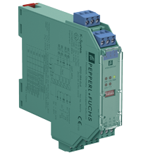
Switch Amplifier KFD2-SRA-Ex4
- 4-channel isolated barrier
- 24 V DC supply (Power Rail)
- Dry contact or NAMUR inputs
- 50 % less wiring, 2:1 technology
- Relay contact output
- Line fault detection (LFD)
- Reversible mode of operation


Quantity

Free Shipping
Purchase on Account

Please note: All product-related documents, such as certificates, declarations of conformity, etc., which were issued prior to the conversion under the name Pepperl+Fuchs GmbH or Pepperl+Fuchs AG, also apply to Pepperl+Fuchs SE.
Download the complete datasheet as a PDF:
Datasheet excerpt: Technical data of KFD2-SRA-Ex4
| General specifications | ||
|---|---|---|
| Signal type | Digital Input | |
| Supply | ||
| Connection | Power Rail or terminals 14+, 15- | |
| Rated voltage | 19 ... 30 V DC | |
| Ripple | ≤ 10 % | |
| Rated current | 45 ... 70 mA | |
| Power dissipation | 1.2 W | |
| Input | ||
| Connection side | field side | |
| Connection | terminals 1-, 2+, 3-; 4-, 5+, 6- | |
| Rated values | acc. to EN 60947-5-6 (NAMUR), see manual for electrical data | |
| Open circuit voltage/short-circuit current | approx. 8 V DC / approx. 8 mA | |
| Switching point/switching hysteresis | 1.2 ... 2.1 mA / approx. 0.2 mA | |
| Pulse/Pause ratio | min. 35 ms / min. 35 ms (non-AC operation) min. 70 ms / min. 70 ms (AC operation) | |
| Line fault detection | breakage I ≤ 0.15 mA , short-circuit I > 6 mA | |
| Output | ||
| Connection side | control side | |
| Connection | output I: terminals 7, 8 ; output II: terminals 8, 9 ; output III: terminals 10, 11 ; output IV: terminals 11, 12 | |
| Output I ... IV | Signal I ... Signal IV ; relay | |
| Contact loading | 253 V AC/2 A /cos φ > 0.7; 40 V DC/2 A resistive load; | |
| Energized/De-energized delay | approx. 30 ms / approx. 30 ms | |
| Mechanical life | 5 x 10⁶ switching cycles | |
| Collective error message | Power Rail | |
| Transfer characteristics | ||
| Switching frequency | ≤ 10 Hz (non-AC operation) ≤ 3 Hz (AC operation) | |
| Galvanic isolation | ||
| Input/Output | reinforced insulation according to IEC/EN 61010-1, rated insulation voltage 300 Veff | |
| Input/power supply | reinforced insulation according to IEC/EN 61010-1, rated insulation voltage 300 Veff | |
| Output/power supply | reinforced insulation according to IEC/EN 61010-1, rated insulation voltage 300 Veff | |
| Output/Output | basic insulation according to IEC/EN 61010-1, rated insulation voltage 300 Veff | |
| Indicators/settings | ||
| Display elements | LEDs | |
| Control elements | DIP switch | |
| Configuration | via DIP switches | |
| Labeling | space for labeling at the front | |
| Directive conformity | ||
| Electromagnetic compatibility | ||
| Directive 2014/30/EU | EN 61326-1:2013 (industrial locations) | |
| Low voltage | ||
| Directive 2014/35/EU | EN 61010-1:2010 | |
| Conformity | ||
| Electromagnetic compatibility | NE 21:2006 | |
| Degree of protection | IEC 60529:2001 | |
| Input | EN 60947-5-6:2000 | |
| Ambient conditions | ||
| Ambient temperature | -20 ... 60 °C (-4 ... 140 °F) | |
| Mechanical specifications | ||
| Degree of protection | IP20 | |
| Connection | screw terminals | |
| Mass | approx. 150 g | |
| Dimensions | 20 x 119 x 115 mm (0.8 x 4.7 x 4.5 inch) (W x H x D) , housing type B2 | |
| Height | 119 mm | |
| Width | 20 mm | |
| Depth | 115 mm | |
| Mounting | on 35 mm DIN mounting rail acc. to EN 60715:2001 | |
| Data for application in connection with hazardous areas | ||
| EU-type examination certificate | ZELM 99 ATEX 0009 | |
| Marking |  II (1)G [Ex ia Ga] IIC II (1)D [Ex ia Da] IIIC I (M1) [Ex ia Ma] I II (1)G [Ex ia Ga] IIC II (1)D [Ex ia Da] IIIC I (M1) [Ex ia Ma] I |
|
| Input | Ex ia IIC | |
| Voltage | 10 V | |
| Current | 14 mA | |
| Power | 35 mW (linear characteristic) | |
| Supply | ||
| Maximum safe voltage | 40 V DC (Attention! Um is no rated voltage.) | |
| Output | ||
| Contact loading | 230 V AC + 10 % / 2 A / 100 VA / cos φ ≥ 0.7; 40 V DC / 2 A resistive load | |
| Fault indication output | ||
| Maximum safe voltage | 40 V DC | |
| Galvanic isolation | ||
| Input/input | not available | |
| Input/Output | safe electrical isolation acc. to IEC/EN 60079-11, voltage peak value 375 V | |
| Input/power supply | safe electrical isolation acc. to IEC/EN 60079-11, voltage peak value 375 V | |
| Directive conformity | ||
| Directive 2014/34/EU | EN IEC 60079-0:2018+AC:2020 , EN 60079-11:2012 , EN 50303:2000 | |
| International approvals | ||
| UL approval | ||
| Control drawing | 116-0145 | |
| IECEx approval | ||
| IECEx certificate | IECEx TUN 04.0003 | |
| IECEx marking | [Ex ia Ga] IIC, [Ex ia Da] IIIC, [Ex ia Ma] I | |
| General information | ||
| Supplementary information | Observe the certificates, declarations of conformity, instruction manuals, and manuals where applicable. For information see www.pepperl-fuchs.com. | |
Classifications
| System | Classcode |
|---|---|
| ECLASS 13.0 | 27210121 |
| ECLASS 12.0 | 27210121 |
| ECLASS 11.0 | 27210121 |
| ECLASS 10.0.1 | 27210121 |
| ECLASS 9.0 | 27210121 |
| ECLASS 8.0 | 27210121 |
| ECLASS 5.1 | 27210121 |
| ETIM 9.0 | EC001485 |
| ETIM 8.0 | EC001485 |
| ETIM 7.0 | EC001485 |
| ETIM 6.0 | EC001485 |
| ETIM 5.0 | EC001485 |
| UNSPSC 12.1 | 32101514 |
Details: KFD2-SRA-Ex4
Function
This isolated barrier is used for intrinsic safety applications. It transfers digital signals (NAMUR sensors/mechanical contacts) from a hazardous area to a safe area.
Each sensor or switch controls one form A normally open relay contact for the safe area load. A special 2:1 wiresaving technology is available on this isolator, reducing field wiring by 50 %.
Switch S1 is used to enable or disable line fault detection of the field circuit. The 2:1 mode is selected with switch S2 while the remaining switches, S3 ... S6, are used for reversing the normal output state of the relays.
A unique collective error messaging feature is available when used with the Power Rail system.
Informative Literature: KFD2-SRA-Ex4
| Literature | Language | File Type | File Size |
|---|---|---|---|
| Application Report - Biological Cleaning of Wastwater and Secondary Sedimentation Stage | ENG | 566 KB | |
| Application Report - Energy Generation in Wastwater Treatment Plants | ENG | 532 KB | |
| Application Report - Generating Electricity in Coal-Fired Power Plants | ENG | 412 KB | |
| Application Report - Sand Trap and Preliminary Sedimentation Stage | ENG | 448 KB | |
| Application Report - Screening Systems in Sewage Treatment Plants | ENG | 577 KB | |
| Application Report - Sicherer Brennstofftransport in Kohlekraftwerken | ENG | 391 KB | |
| Application Report - Water Inlet in Wastewater Treatment Plants | ENG | 526 KB |
Product Documentation: KFD2-SRA-Ex4
| Safety and Security Documentation | Language | File Type | File Size |
|---|---|---|---|
| Instruction manual | ENG | 161 KB | |
| Manuals | |||
| Manual | ENG | 3685 KB | |
Design / Simulation: KFD2-SRA-Ex4
| CAD | Language | File Type | File Size |
|---|---|---|---|
| CAD 3-D / CAD 3-D | ALL | STP | 2510 KB |
| CAD Portal / CAD Portal | ALL | LINK | --- |
| CAE | |||
| CAE EPLAN Data Portal / CAE EPLAN Data Portal | ALL | LINK | --- |
| CAE EPLAN macro EDZ / CAE EPLAN Makro EDZ | ALL | EDZ | 1512 KB |
Approvals: KFD2-SRA-Ex4
| Certificates | Certificate No. | Language | File Type | File Size |
|---|---|---|---|---|
| Australia SIMTARS | ANZEx 13.2005 | ALL | 296 KB | |
| Canada UL cUL | E106378 cUL (QUZW7) | ALL | LINK | --- |
| Europe ZELM ATEX Category (1) GD ATEX Category (M1) | ZELM 99 ATEX 0009 | ALL | 1585 KB | |
| India PESO (India) CCOE | A/P/HQ/KA/104/5914 (P515190) | ALL | 100 KB | |
| SITIIAS CCC Ex Certificate | 2021322316003615 (Singapore) | ALL | 1072 KB | |
| South Africa MASC | MASC MS/19-6054 | ALL | 665 KB | |
| TUV Nord IECEx Certificate of Conformity | IECEx TUN 04.0003 | ALL | LINK | --- |
| USA Canada UL Hazardous Location Certificate of Compliance cULus UL E106378 | CoC 20160608 - E106378 RepRef 19970520 | ALL | 246 KB | |
| USA UL | E106378 UL (QUZW) | ALL | LINK | --- |
| United Kingdom CML UK-Type Examination Certificate UKEX Category (1) D UKEX Category (1) G UKEX Category (M1) | CML 21UKEX2936 | ALL | 148 KB | |
| Control Drawings | ||||
| Control drawing UL / Control drawing UL | ALL | 165 KB | ||
| Declaration of Conformity | ||||
| EU Declaration of Conformity (P+F) / EU-Konformitäterklärung (P+F) | DOC-0255C | ALL | 109 KB | |
Associated Products: KFD2-SRA-Ex4
| Matching System Components | ||||||
|---|---|---|---|---|---|---|
|
||||||
|
||||||
|
||||||
|
||||||
|
||||||
|
||||||
| Accessories | ||||||
|
||||||
|
||||||
|
||||||
|
||||||
|
||||||
|
||||||


 Contact Us


- Ask an Expert
- Cross Reference Request
- Check order status
- News
- Subscribe to Gate-Way, our Process Automation Division e-newsletter
- Service Level Agreements for ecom instruments
- Where to Buy our Products
- Browse Literature
- Technologies
- Control System Solutions
- Download Technical Documents
- Press Releases
- International Trade Shows

Choose from various selection criteria like safety integrity level, performance level, device function, and signal type and find the SIL/PL assessed device that you are looking for.


Pepperl+Fuchs Inc.
1600 Enterprise Parkway
Twinsburg, OH 44087
USA
- responsible for Canada -
sales@us.pepperl-fuchs.com
 +1 330 425-3555
Pepperl+Fuchs is a leading developer and manufacturer of electronic sensors and components for the global automation market. Continuous innovation, enduring quality, and steady growth have been the foundation of our success for more than 70 years. Pepperl+Fuchs employs 6,300 people worldwide and has manufacturing facilities in Germany, USA, Singapore, Hungary, Indonesia and Vietnam, most of them ISO 9001 certified.